1. OVERVIEW
U-Boot Beton® Design Software is the ideal tool for designing of voided slabs without drop panels or drop beams.
The voided slab with the U-Boot Beton® formwork is made up of a mutually orthogonal and interconnected rib pattern, integral with a continuous slab at the intrados and one at the extrados.
The structural behavior of a voided slab with U-Boot Beton® elements is the bidirectional one characteristic of the full-concrete slab, with the advantage of a substantial reduction in weight that allows savings both in concrete and steel reinforcement.
For this reason, U-Boot Beton® is the ideal solution for the realization of slab on large spans that can bear high overloads.
U-Boot Design Software meets all the needs of designers who deal with the study of the voided slabs with the U-Boot Beton® system of Daliform Group, providing them with all the necessary data to properly carry out the structural analysis of the slab designing.
In particular, the U-Boot Design Software, depending on the user-set floor configuration, provides:
– All the geometric and inertial characteristics of the resistant cross-section;
– Inertia and Weight Modifiers to consider in FEM Analysis for “Plate” elements of the same thickness;
– Resistant Moment and Shear resistant values;
– Detailed and complete CAD cross sections which report all the information implemented by the user;
– A comprehensive Report of all Input and Output data.
All of the above information represents a valuable support to the designer and can be used to implement numerical analysis conducted with the help of the most commonly used structural calculation software.
The Software is available for free at the link in the homepage of the website www.daliform.com

Figure 1 – Access from the ‘Technical Support’ page or the ‘U-Boot Beton’ product page.
2. LOGIN
Multilanguage access.
A. If you already have an account login with credentials activated by the confirmation email;
B. Create an account by following the simple steps of the registration form.
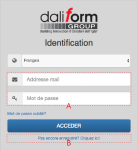
Figure 2 – Login.
3. USER INTERFACE
Quick and intuitive graphical interface.
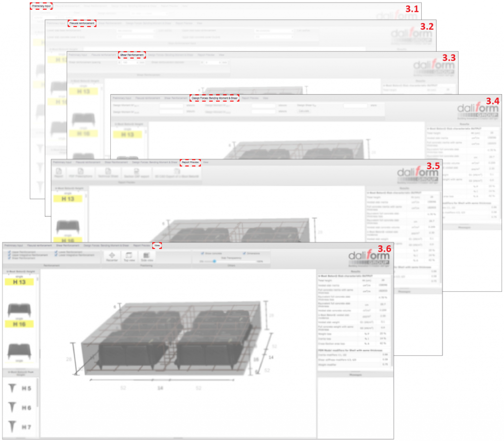
3.1 Preliminary Input
In the main window, the User can edit and insert, in a completely independent manner, the geometrical characteristics of the slab, the materials and the reference standards for the calculation of design resistant forces.
1.A. Standards – EN 1992-1-1_2005 or ACI-318-11;
1.B. Materials – Concrete class and Steel grade reported to the standard;
1.C. Geometric characteristics input- by Free For or Simplified (Wizard) form;
1.D. Scrolling graph menu;
1.E. Characteristics Output;
1.F. 3D View – Zoomable and editable by dimensions.
The 3D model on the main screen automatically displays any change to the geometry of the configuration.
Individual changes to the height of the U-Boot formwork, the height of the feet (thickness of the lower slab therefore), can be easily conducted using the graphical “scrolling” menu on the left of the screen.

Figure 3 – Preliminary Input.
On the right part of the screen, the table “Results” automatically updates the geometric and inertial characteristics of full and lightened section. It also shows the modifiers of inertia and weight to be considered in FEM modeling of the slab, according to the most common approach that provides for shell elements of the same slab thickness, both for the full concrete parts and for those lightened.
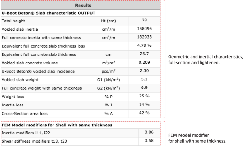
Figure 4 – Geometric and inertial characteristics.
Here below an example of implementation of the modifiers determined by the application, in a FEM Midas Gen model, having considered plate elements of the same thickness.

Figure 5 – Example of implementation of modifiers in a 3D-FEM model.
3.2 Flexural Reinforcement
In this section, it is possible to choose and enter the type of steel reinforcement as base or integrative reinforcement; the latter, distinguishing between integrations in the slab thickness or inside the ribs.
2.A. Lower slab base reinforcement;
Concrete cover Ci [cm] from bottom side of slab.
2.B. Upper slab base reinforcement;
Concrete cover Cs [cm] from top side of slab.
2.C. Resistant moment calculation – Output.

Figure 6 – Flexural reinforcement.

Figure 7 – Base reinforcement – Input.
According to the geometrical characteristics, and the amount base reinforcement, the software calculates the section Resistant Moments – MR [kNm/m] and [kNm].

Figure 8 – Resistant moment calculation – Output.
Where:
MR [kNm/m]: Resistant Moment per meter of width;
MR [kNm]: Resistant Moment for a width equal to the rib’s axis-to-axis distance;
X [mm]: Depth of neutral axis;
C [cm] from axis: Position of the steel bar with respect to the lower or upper side respectively;
φ [mm]: Bars diameter;
n°: Number of steel bars for each meter of width;
Ai [cm2/m]: Steel reinforcement area for each meter of width;
Concrete Cover Check: OK/NO, the software checks for the presence of the minimum concrete cover.
2.D. Lower integration in mash – Direction 1-1 (X-X);
2.E. Lower integration in mash – Direction 2-2 (Y-Y);
2.F. Upper integration in mash – Direction 1-1 (X-X);
2.G. Upper integration in mash – Direction 2-2 (Y-Y);

Figure 9 – Resistant moment calculation.
Where:
MR [kNm/m]: Resistant Moment per meter of width;
MR [kNm]: Resistant Moment for a width equal to the rib’s axis-to-axis distance;
X [mm]: Depth of neutral axis;
C [cm] from axis: Position of the steel bar with respect to the lower or upper side respectively;
φ [mm]: Bars diameter;
n°: Number of steel bars for each meter of width;
Ai [cm2/m]: Steel reinforcement area for each meter of width;
Concrete Cover Check: OK/NO, the software checks for the presence of the minimum concrete cover.
2.H. Lower integration in rib – Direction 1-1 (X-X);
2.J. Lower integration in rib – Direction 2-2 (Y-Y);
2.K. Upper integration in rib – Direction 1-1 (X-X);
2.L. Upper integration in rib – Direction 2-2 (Y-Y);

Figure 10 – Resistant moment calculation.
Where:
Nr. of Reinf. in Ribs: Number of reinforcement in ribs
MR [kNm/m]: Resistant Moment per meter of width;
MR [kNm]: Resistant Moment for a width equal to the rib’s axis-to-axis distance;
X [mm]: Depth of neutral axis;
C [cm] from axis: Position of the steel bar with respect to the lower or upper side respectively;
φ [mm]: Bars diameter;
n°: Number of steel bars for each meter of width;
Ai [cm2/m]: Steel reinforcement area for each meter of width;
Concrete Cover Check: OK/NO, the software checks for the presence of the minimum concrete cover.
In the case of integrations in ribs, it is necessary to enter the value of diameter first and subsequently the number of bars. The software will indicate the maximum allowable number of bars in relation to the width of the ribs.
3.3 Shear reinforcement
In this section, you can insert the shear reinforcement by modifying the rebar diameter and the spacing too. The software verifies that the minimum/maximum spacing of standard is always guaranteed.
3.A. Shear reinforcement spacing;
3.B. Shear reinforcement diameter;
3.C. Cross-section Geometric Characteristics;
3.D. Shear resistance without reinforcement;
3.E. Shear resistance with shear reinforcement.

Figure 11 – Shear reinforcement.

Figure 12 – Shear reinforcement.
The software automatically returns the design shear resistance values of section with and without reinforcement.
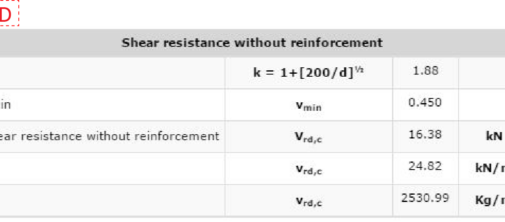
Figure 13 – Shear resistance without reinforcement.
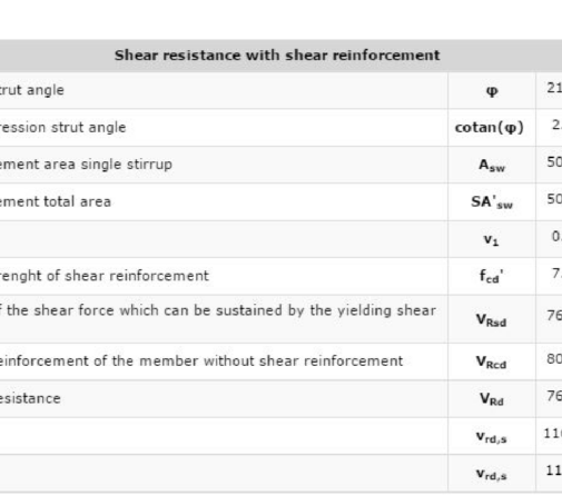
Figure 14 – Shear resistance with reinforcement.
3.4 Desing Forces: Bending Moment & Shear
In this section the user can enter the design forces values determined with the help of any 3D-FEM software; the application will compare them with the corresponding resistant values that will have previously been calculated based on the user-set geometry.

Figure 15 – Design forces.

Figure 16 – Design forces – Input.
Enter the design forces, press “calculate”, and check:

Figure 17 – Design forces Check – Output.
3.5 Report Preview

In section, “Report Preview” the user has several useful tools available:

3.6 View
In the main window of the application, there is always the 3D model of the slab that the user is realizing. The template is automatically updated to any change (geometry, steel reinforcement, etc.) that the user makes. In the “view” section, there are several utilities.
6.A. Let you view or not each order of steel reinforcement (base, integrations, shear);
6.B. They return the model to pre-set positions:
* Use the left button of mouse to rotate the model;
* Use the right button of mouse to move (pan) the model;
* Use the scroll of mouse to zoom in or out the model;
6.C. Viewing options:
* Show or hide the concrete;
* Set the transparency of concrete;
* Show or hide the dimension.

Figure 18 – View section.
All dimensions in the model, except the fixed ones (in grey), can be used to modify the corresponding geometrical parameter of the slab, as shown in the figure below.
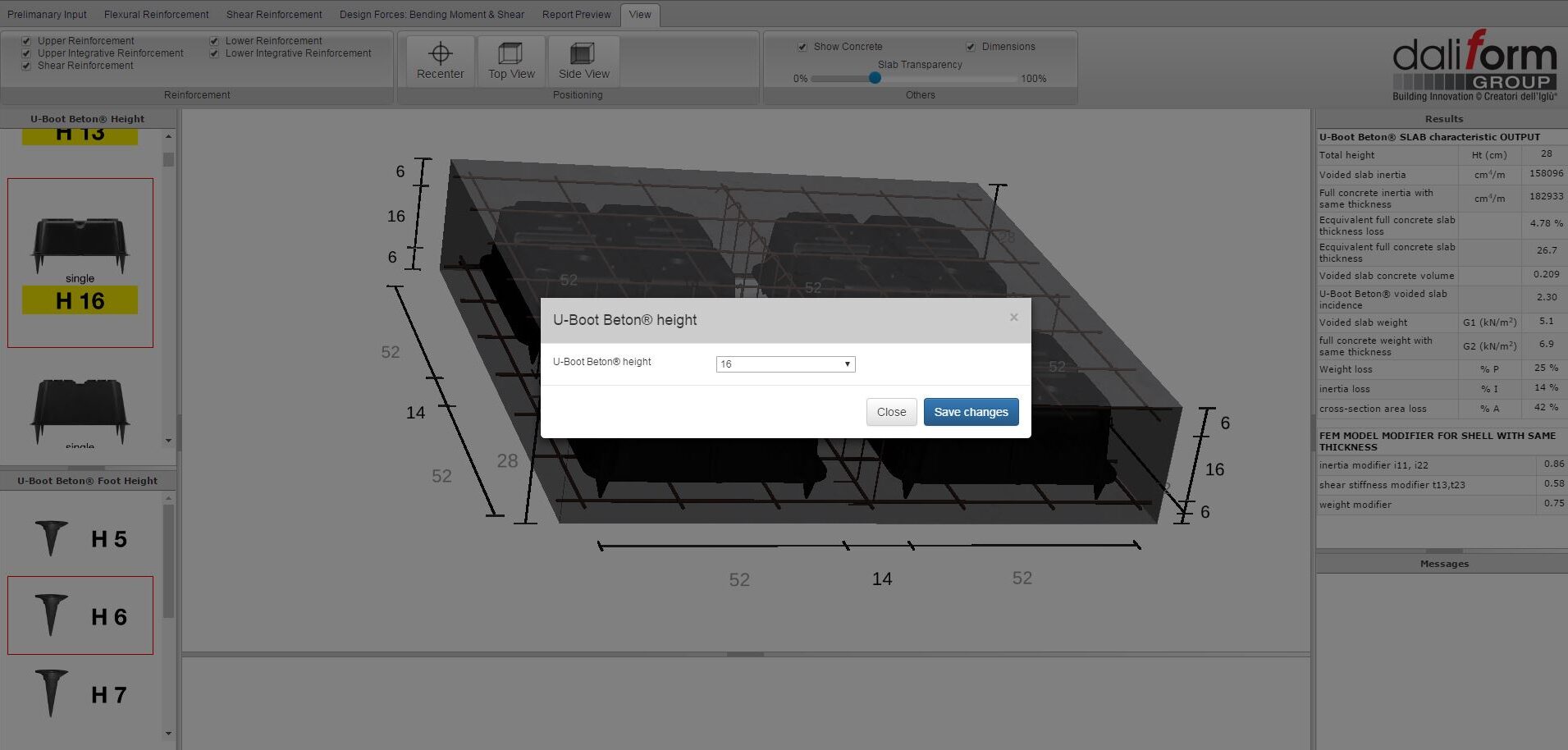
Figure 19 – Edit model by dimensions.
Figure 20 – Edit U-Boot Beton® height by dimensions.
